Holly-Wood.it  
    Brick 1 x 3
Brick 2 x 2 Corner    
  Brick 1 x 1  
[ english ] deutsch ] italiano ]
 
  Home > MLCad > Tutorial: Digital building - Page 2 of 9  
   
  Page <Previous 1 2 3 4 5 6 7 8 9 Next>
 

Adding parts

   
  Screenshot 4
   
  12. To add the second Plate 2 x 2 with Wheels Holder you could obviously pick it from the Parts Preview pane and place it in one of the building panes but I'd like to show you an alternative way. Hold the CTRL key while you click and drag the already positioned part in the building area. Upon releasing the mouse-button a copy of the part will be inserted at the new position. This method is most efficient when you have to duplicate and move multiple parts at once.  


Graphical aides


  13. The newly added part will show up also in the Project Parts List. This pane keeps track in a textual way of all the parts used in a project as well as so-called Meta-Commands which trigger certain function in the program. You'll find information about color, the position, how the part is rotated in prospect of the origin or its number. The list is in processing order. This means: When Draw To Selection Only Draw To Selection Only Button is set in the Mode bar or ticked in Settings > Draw to Selection the program goes through this list from top to bottom, executing it line by line. The Project Parts List is the ideal place when it comes down to select, copy and delete parts, as well as changing the execution order. Note how the second Plate differs in the figures on the Z-axis.  
  14. Since the border of the panes overlaps the new part in the Top view the zoom has to be adjusted. MLCad allows zooming in four different ways. Neither of them changes the project itself, only the way how the program displays the project:
  • Zooming in all panes at the same time
    All panes can be set to a certain zoom factor at the same time or the zoom factor of all panes can be calculated for best fit of the project within the views. Select a zoom factor in Settings > Zoom > ... or click the corresponding button in the Zoom bar Zoom Bar.
  • Zooming only in the activated pane using the mouse
    This is the best way to perform zooming. Move the mouse over the view pane you want to change - in this case Top – and left-click. The now activated pane will be highlighted with a red border. Move the scroll wheel to zoom in or out. Holding the scroll wheel button down allows panning.

    NOTE! If you haven't got a mouse with a scroll wheel hold down the SHIFT+CTRL key. Move the mouse with the pressed left mouse-button up and down to zoom in and out. The activated pane will be highlighted with a red border. Release the mouse-button and the SHIFT+CTRL key once the project is shown in the desired size.

  • Zooming in one pane using the contextual menu
    Some consider this the quickest way to perform zooming. Move the mouse over the view you want to change. Press the right mouse-button and navigate to Zoom in the pop-up menu. Select one of the options from the sub-menu.
    The menu item Set... allows you to manually enter a zoom factor, while Fit calculates a zoom factor to have the full project centered in the pane.
  • Zooming via Zoom Mode
    This mode is used to permanently allow zooming inside the viewing panes but move control commands and editing facilities are disabled in this mode. You might add parts to the project but selecting, deleting or copying can be done exclusively via the Project Parts List. To activate Zoom Mode you can either select the menu Settings > Zoom Mode, or you click on the corresponding button Zoom Mode Button in the Mode bar. Also pressing the F5 key activates this mode. Move the cursor over a pane. Press and hold the left mouse-button. Move the mouse up and down to zoom in and out. Release the mouse-button. Optionally zoom another pane. Deactivate Zoom Mode by switching to another mode.

Use the method you feel most comfortable with and center the two plates in all panes.


  Screenshot 5
   
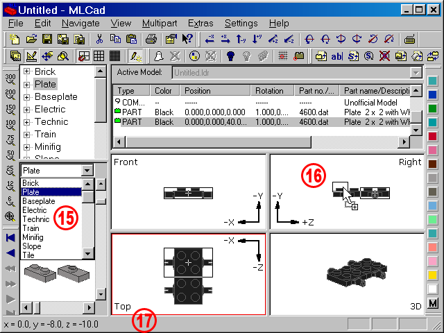
  15. You might browse the Parts Preview instead of the Parts Tree if you know what the part looks like, but don't know how it is named in the LDraw Library. Use the drop-down box at the top or the slider at the bottom of the pane to navigate through the sub-directories. Use the slider at the right-hand side to browse through the parts in a sub-directory. Clicking with the right mouse-button in the preview switches between a larger and smaller representation. The Plate 1 x 2 we are look for is just some clicks on the slider bar away.

NOTE! In the Parts Preview pane the scroll wheel will by default always browse through the sub-directories. There is no setting to browse the parts in a sub-directory with the scroll wheel.
 Brick 2x2
  16. Drag the part to the pane showing the project from the right side. Obviously you could also drop it in the Front, Top or 3D view pane but in this case only the Right view pane is the right choice. It will save you additional positioning because you are able to define two of the coordinates in one move. In 3D the Plate would get X=0, Y=0, Z=0. In Top you could define the X- and Z-coordinates but not the part's height. Since the Plate 1 x 2 is on the same line as the Plate 2 x 2 with Wheels Holder you would have to move it up in a second step. In Front you could place the part higher, but the program would copy the position of the previous part on the Z-axis to the newly added part. This would result in an offset of 40 LDUs. Placing the Plate 1 x 2 in the Right view pane you can define the coordinates on the Y- and Z-axis while the value of the X-axis - virtually sticking out from the monitor and therefore invisible - would be copied from the previous part in the Project Parts List. Sounds complicated. Get it a try ;-)  
  17. While you are hovering over the panes the Status bar at the bottom of the window shows you the actual coordinates the part would get if drop in that position. The bar will also show you a short help comment about the menus or the buttons in the toolbars. When you move the cursor above a part in the Parts Preview the Status bar will tell the part's number as well as its name...  


Handling colors


 Brick 3x3 Screenshot 6
 
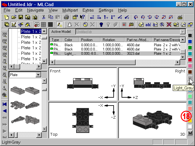
  18. The Status bar will also tell you the color name when you point the cursor to a color button in the Color bar. Using the bar is by far the fastest way to change the color of a part. Just make sure the part you want to color is selected and hit the button in the Color bar. The part will be colored in the building area and the name in the Color column in the Project Parts List will change. If the desired color cannot be found among these 16 color buttons you'll have to call up MLCad's color dialog. The dialog gives you access to all the colors used by the LEGO Company so far.

NOTE! The colors in the Color bar are the original core colors used by the LDraw program written by James Jessiman back in 1995 and differ from the RGB shadow colors used by the LEGO Group. At the time the colors have been defined by Jessiman no color definitions form the LEGO Group where available and the chosen RGBs where then considered the closest match. In the 2009-update of the color chart it has been decided to maintain the old color definitions to guarantee backwards compatibility.

The colors are: Black, Blue, Green, Dark Cyan, Red, Magenta, Brown, Grey, Dark Grey, Light Blue, Light Green, Cyan, Light Red, Pink, Yellow and White and once you have learned how the color dialog works you'll be taught how to change them to something else.
Brick 1x4
 
  (The screenshot shows all menus and dialogs in one composed image).
Screenshot 7
 
   
  Brick 37x3
19. There are several ways to call up the Color dialog once the part has been selected:
  • Select Edit > Color... from the menu or simply hit C.
  • Right-click in the panes in the building area and select Change color... from the pop-up menu.
  • Click the More button Color More Button in the Color bar. (In case the buttons are aligned to just one vertical row you'll read only M at the bottom).
  • Right-click the part you want to color in the Project Parts List and select Change color... from the pop-up menu.
top  
20. You might wonder why by default you are presented with a tab sorting the colors by number and not by name or category such as transparent or rubber? This has historical reasons going back to the very first days of the LDraw System of Tools. You might download and print the color chart below set up by Philippe 'Philo' Hurbain to get a better overview:
 
LDraw Color Chart Thumbnail   Download icon LDraw_Color_Chart.pdf   (7.92 MB)
 
Select the Name tab if you feel more comfortable with names. MLCad extracts the name from a file called LDConfig.ldr which after a rework in 2009 now comes with a naming scheme that is consistent with the colors used at Bricklink.com.
21. Use the slider to browse to the next row of colors. Those will be the transparent colors in the Number tab.
22. Selecting a color you'll get more information such as the color number and its name. If you are tired of browsing through the palette and already know the number of the color you want to use, just type in the number in the Color number field.

NOTE! Entering the number directly won't give visual feedback of any kind, not the color name nor a color preview.
23. Hit OK to confirm your choice and exit the color dialog.

NOTE! Use the color dialog also to permanently change the default colors in the Color bar. You might substitute color 7 - Light_Gray with the nowadays used color 71 - Light_Bluish_Gray or replace rare colors like Salmon or Bright_green with transparent or chrome colors.
Right-clicking the color button you want to change will bring up the color dialog. Select a color as you would do for a part, okay-ing, MLCad will store the information in its settings.
  Page <Previous 1 2 3 4 5 6 7 8 9 Next>
  Brick 1x3
All content is provided as is, with no warranty stated or implied regarding the quality or accuracy of any content on or off this site.
LEGO® is a trademark of the LEGO Group of companies which does not sponsor, authorize or endorse this site.